I. General
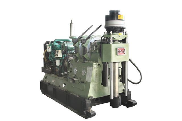
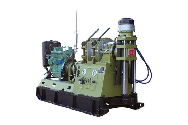
XY-4 Core Drill is a new type high speed diamond core drill designed according to the development of geological work in China and developed to meet the requirements of clients.
XY-4 Core Drill has been identified in 1976, and rewarded with the Chinese National Silver Medal in 1988. The XY-4 model has been sold all over the country.
XY-4 Core Drill can be driven by Deutz F4L 912 diesel engine or 30KW electric motor. The drill has 8 rotary speed stage, the Max, speed 1588 rpm, the min speed 101 rpm, so it is suitable for various drilling for solid mineral deposits with diamond or tungsten-carbide tipped bit. It is also suitable for engineering geological subterranean water explorations as well as explorations of shallow layer oil and natural gas, and can be used to drill holes for ventilation and drainage of main gallery.
II. Main Features
1.The rig is in higher rotational speed and rational range of rotational speed; large torque in low speed.
2.The drill is suitable in the mountain area because of light weight for easy transport and convenient disassembly (to be disassembled into nine parts).
3.With compact structure and reasonable layout, and all exposed, non overlapped components, it is easier for maintenance and repair.
4.It is convenient for you to treat trouble with two reverse speeds. With low center of gravity, the rig is reliable and stable in high speed drilling.
5.The operation levers are concentrated, so the operations are reliable and convenient.
6. Fitted with meters, the circumstances can be controlled easily in hole.
7. The transmission is separately driven for drill rig and mud pump; it is easier for the location arrangement with less space occupying.
III. Speacifications
1.Basic parameter
Depth of hole
Φ42mm(1.65inch) drill rod -----------------1000 m(3280 feet)
Φ50mm(1.97inch) drill rod ------------------700 m (2296 feet)
Angle range--------------------------------------------0°-360°
Dimensions (L×W×H) ------------------------------2710×1100×1750mm(106.7×43.3×68.9 inch)
Weight (without power unit) ----------------------1500 kg (3308 lb)
2.Swivel head Spindle speed (r/min)
Ⅰ. Driven by power machine speed 1500 r/min
Forward low speed----------------101; 187; 267; 388
high speed----------------311; 574; 819; 1191
Reverse low speed------------------83
high speed----------------251
Ⅱ. Driven by power machine speed 2000 r/min
Forward low speed ---------------------135; 250; 355; 517
high speed---------------------415;765;1090;1588
Reverse low speed-----------------------110
high speed----------------------338
Spindle stroke -----------------------------------------600 mm (23.62 inch)
Spindle lifting capacity -------------------------------Max. 80 kN (17984 lbf)
Spindle pull down force ------------------------------Max.60 kN (13488 lbf)
Spindle torque by power machine efficiency 29.4 kW(39.43HP), speed 1500 r/min
2640;1410;980;660 N·m (1946;1037;722;486 lbf·ft)
830;440;300;200 N·m (1946;1037;722;486 lbf·ft)
Spindle I. D. ------------------------68 mm (2.68 inch)
3.Hoist Lifting capacity (single line)
By motor 29.4 kW (39.4HP), 1500 r/min ------------Max.30 kN (6744 lbf)
By diesel 44.1kW (59.1HP) , 2000 r/min ------------Max.33 kN (7418 lbf)
Lifting speed (3rd layer)
By motor 39.4 kW(52.8HP) , 1500 r/min ----0.82;1.51;2.16;3.15m/s(2.69;4.95;7.08;10.33 feet/s)
By diesel 44.1kW (59.1HP ), 2000 r/min ----1.09;2.02;2.89;4.18 m/s (3.58;6.63;9.48;13.71 feet/s)
Wire rope dia. -----------------------------------16 mm (0.63 inch)
Drum capacity --------------------------------90 m (295 feet)
Drum dia. ----------------------------------------285 mm (11.22 inch)
Brake rim dia. ----------------------------------490 mm (19.29 inch)
Brake band ------------------------------120 mm (4.72 inch)
4.Travelling device Retraction cylinder stroke------------------------------------460 mm (18.11 inch)
Distance between drill and hole------------------------------310 mm (12.20 inch)
5.Oil pump Displacement --------------------------------------------------20 L/min (5.28 US gallons/min)
Speed (r/min)--------------------------------------------------1500
Working pressure --------------------------------------------8 MPa (1160 psi)
Max. Pressure ------------------------------------------------12 MPa (1742 psi)
6.Power unit
| Name type | Electric motor Y200L-4 | Diesel engine Deutz F4L 912 |
| Efficiency | 30 kW (40HP) | 38 kW (51HP) |
| Speed (r/min) | 1470 | 1800 |
IV. Driving System
The drill’s transmission system consists of mechanic driving system and hydraulic transmission system. Here only elucidate driving system in simple works. The rotation of power unit is driven toward speed change box by elastic coupling, then will be change into 4 forward speeds and 1 reverse speed. The output shaft of speed change box is connect input shaft of transfer case with universal coupling , then the rotation will be driven toward hoister or swivel head. By operate the transfer case speed change level, the swivel head have 8 forward speeds and 2 reverse speeds.
The oil pump is driven by V-rubber belt which is driven by band pulley.
V.Construction
XY-4 Core drill consists of seven basic assembly components:
1.Swivel head assembly
2.Transfer case assembly
3.Hoister assembly
4.Speed change box assembly
5.Hydraulic system
6.Power unit(incl. clutch)
7.Frame In order to divide and set up conveniently, these components are joined by connectors such as spline, elastic couplong, universal coupling etc. The drill is equipped with hydraulic chuck and lower hand chuck. In the course of normal operating, the lower chuck is no use, when drilling deep hole or pulling tools out of the hole, both chucks are used at the same time. On the instrument board are fitted with drilling pressure gauge, hydraulic systems pressure gauge and indicating meter. The drilling pressure is judged by pressure gauge and the pressure of which pull rods out of hole, loose hydraulic chuck and make up or break-out tools and judged by system pressure gauge.
VI. Drill control system
Before operating drill for the first time, it is essential to have a good knowledge of various control levers’ applications and positions so you will avoid damages. Upon operating levers, please pay attention to following cases.
1.Before starting drill, you should make sure that all lever are in right position, such as: at this moment, the clutch lever is in "off” and every speed change level should be in "neutral position” etc.
2.Speed can be only changed by shifting lever of the speed change box or the transfer case, after setting the clutch lever to "off” position and the gear speed is decreasing or stopping.
3.The hoister’s lifting lever and braking lever can’t be operated at the same time.
4.In the multi-changeover valve block, lever can’t be operated at the same time except lever of the overflow valve’s boost pressure.
5.Hoisting and lowering rod by the hoister the hoist and drill head clutch lever should be in "neutral gear”.
Telephone (Office): 0086-518-85383089, 0086-518-85383090
Email:sales@hhdrillrig.com
Address:
No.241, South Yuzhou Road, Haizhou Area, Lianyungang, Jiangsu, China
Postcode: 222062
Follow us:

Copyright © H.H. Drill-Tech Drilling Machinery Co., Ltd All Rights Reserved